Integration in inkjet is all about making the most of components to produce the most effective printing or manufacturing machines. Previously we looked at bringing together two of the three fundamental constituents of an inkjet process – the head and substrate. In this article, we’ll be tackling the important factors to consider when it comes to uniting two of them along another side of the inkjet triangle – namely inks and printheads – with particular focus on delivering the inks in a controlled manner.
Inkjet Nozzles & Meniscus
Thermal and piezoelectric heads most commonly used in inkjet development are all about making drops on demand (as opposed to continuous inkjet heads). When drops aren’t wanted then the ink in the nozzle is at rest, and to stop it dripping out under gravity a small negative pressure is applied. This pressure is called the meniscus vacuum, since it holds the ink in the typically cylindrical nozzle with a concave surface determined by the nozzle material, ink surface tension and amount of vacuum.
The schematic below demonstrates the process using time-delay-stitched images from a new drop watching apparatus in the Author’s laboratory, the “Inline” made by Jetxpert. The image was produced in steps of 1 microsecond (1 millionth of a second shown as us) and each separate “slice” is actually a separate droplet ejection made at a frequency of 5kHz so that there is 200us between each ejected droplet. For this simple solvent test fluid, it takes about 1/10th of the drop period for an ink ligament to pull away from the meniscus. This means that, at frequencies higher than 40kHz, the next droplet actuation interferes directly with the ligament break of the preceding one.
[caption id="attachment_6554" align="aligncenter" width="616"]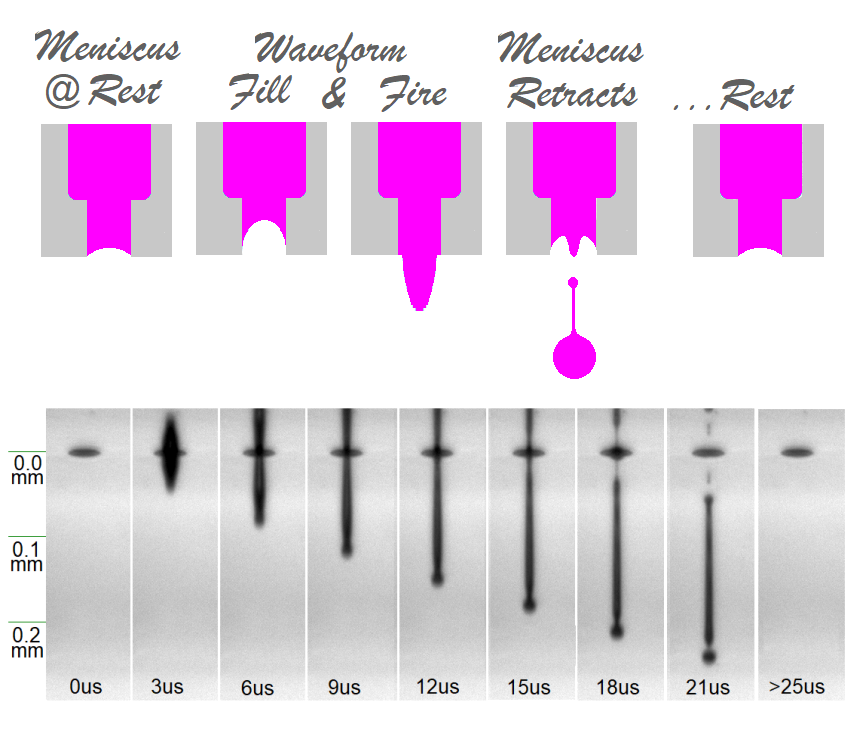 Figure 1 Schematic of an inkjet nozzle at rest (top) and with a Jetxpert Inline Dropwatcher (bottom)[/caption]
For this simple solvent test fluid, it can be seen that it takes about 20us (~ 1/10th of the drop period) for the fluid in the ligament to pull away from the meniscus. Pressure variations in the head during this time can vary the position of break and this influence the droplet position.
The sub-assembly of components that supply ink to the printhead are usually known as Ink Delivery Systems, or IDS and it is an important part of their function to supply a constant meniscus pressure under varying conditions of ink demand by the print head/printer.
In the dropwatcher “stitch” image examples shown as Figure 2 below, we compare the droplet ejection of a UV ink when supplied from a syringe, with meniscus pressure coming from the relative height (gravity), and from an IDS.
The images are really quite similar but the IDS one has slightly more droplet position variation from an imaginary trendline. In dropwatcher images this corresponds to a variation in speed, due to something called the time-of-flight.
[caption id="attachment_6553" align="aligncenter" width="630"]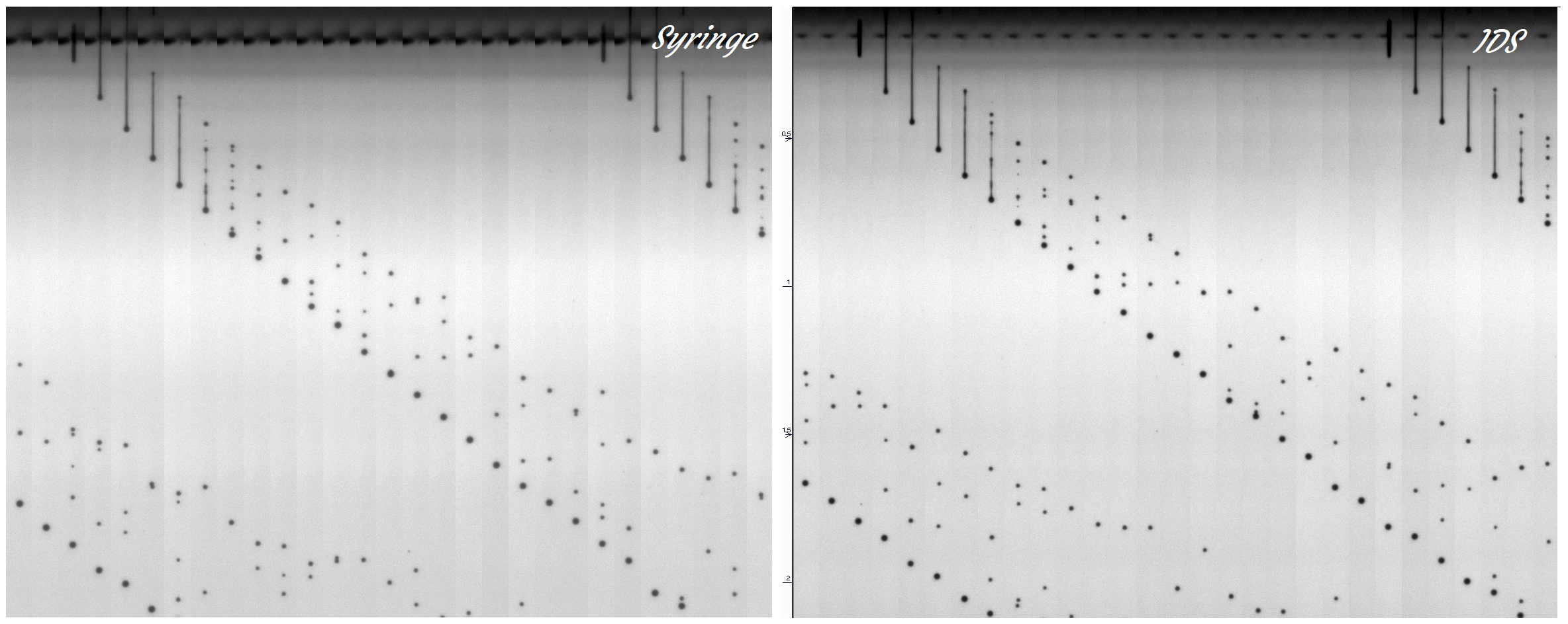 Figure 2. Droplet speed consistency with a control system (right) versus gravity feed from syringe (left).[/caption]
Main IDS Components
Almost all industrial systems with any throughput tend to consume sufficient ink that auto-refiling via pumps is necessary so shall limit our discussion to examples where ink is pumped from a main tank into an intermediate tank (or circuit) and omit the simple gravity arrangement used in some small printers.
The pressure controlling aspect of an IDS is usually based on the pneumatic (air) pressure in the header tank, as shown in the middle image of Figure 3. Normally the pneumatic meniscus pump works against some controlled bleed of air into the tank making two-way control possible. When jetting starts, the meniscus pump works less hard since a vacuum is created by the pumping action of the head. The control goes the other way when the ink pump kicks in to refill the tank when the head starts to consume the ink since the side-effect of that is increased tank pressure.
The particle filters used in an IDS are quite important since they protect the system and the print head and nozzle from undesirable materials that can be accidentally incorporated into the bulk ink during handling, and from any deterioration of the ink over time (shelf life). A bulk filter stops ink from the main tank polluting the system, whilst the “last-chance” filter does what it says and prevents any other debris accumulated in the IDS from reaching the head. It has to be use carefully though, since as it does its job and gets blocked it can create a multitude of issues relating to pressure drops.
Additional “degassing” modules can be used for removal of gas bubbles, which can help with higher frequency operation. These modules are commonly placed in line with the bulk filter, although between the header tank “reservoir” and head is also possible.
The final element is heating and/or cooling, depending on the relationship between ink desired jetting temperature and environmental conditions. For UV inks, heating is common since they are used at 40-55°C but for water-based inks the use of refrigeration is known. In either case, adjustment and control can through direct electrical means (resistive heater, peltier), or through heat exchange (e.g. with water). The point of control can be a specific heater module, the header tank or even the print heads themselves if included by the manufacturer.
Whichever approach is used, it is usual that the ink viscosity changes with temperature so good control is again important to ensure repeatable results. Better than ±1°C at the printhead is desirable. Minimising the extremes of temperature by sensible insulation and design is also advantageous.
[caption id="attachment_6552" align="aligncenter" width="624"] Figure 3. The main components of different ink system designs. ©Imagexpert[/caption]
When recirculating the ink, as used in many print heads like Fuji SAMBA™, we have additional complication, since there are normally two header tanks at different pressures, according to the print head specification. The last schematic in Figure 4 shows this type of example. Looking at independent suppliers in the market, the offerings from Global Inkjet Systems work this way.
Alternatively, liquid pumps can run continuously, and inline ink pressure sensing used to monitor pressure and control the speed of those pumps. The Xaar Hydra™ ink system does this. Finally, some IDS are hybrid and use a combination of pneumatic control and a liquid pump. The compact ink systems (CIMS, Labjet) from Megnajet Ltd that the author uses in his lab operate like this.
Asserting Control
In the example below, which uses the hybrid approach and was used to make the test in figure 2, we can see the periodic pressure variation introduced by the pneumatic vacuum pump used to control the meniscus pressure in a recirculation head.
The peak-to-peak variation is about 3mbar and is dependent on the air volume in the header tank, the air bleed rate and the pressure setting itself. Although some head manufacturers ask for better than this, a head that is this sensitive to meniscus can prove quite difficult to operate at the most demanding frequencies.
[caption id="attachment_6551" align="aligncenter" width="692"]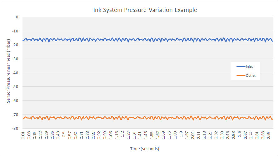 Figure 4. The pressures measured in a real ink circulation system. ©DoDxAct Ltd[/caption]
Notice that the variation is seen also to be correlated on the outlet since the head how a low impedance and this is very print head dependent since some heads require much higher vacuum on the return side due to the presence of restrictors in the ink path.
Whether pneumatic or hydraulic, the pump speeds in the IDS are themselves governed by a software algorithm which has variables chosen to reflect the impedance and response of the system. So adjusting these for each fluid property, such as viscosity, can be an important part of optimsing the system, just like tuning an engine of a race car.
The Takeaway
Good quality inkjet printing relies on the consistent production of droplets from the nozzle, and this in turn requires a consistent, negative, meniscus pressure on the nozzles to be achieved under varying conditions of ink usage and refilling. Thus, the ink system is a critical part of overall design and one which requires a detailed understanding of the printhead requirement and the ink behaviour under stress through pumps, filters, degassers and print heads.
In summary, not only is it ”okay to suck”, but it is an absolute requirement to excel at it. Which is a perfect inkjet paradox.